Posts

Showing posts from July, 2022

Information eg pinouts

Image
 

Real time LDR readings sent to receiver Wemos Mini

Image
 Sent LDR readings to wemos min about 500mm away via ESP Now. The sender uses https://pastebin.com/fKpkv94Y, Sender8 and the receiver uses https://pastebin.com/1xJhw3fa , receiver3with Blink Sender is in the foreground of photo below. Receiver is above metallic pig on window sill. Next put sender with LDR in box or container outside in various positions and check it can send LDR data OK. This would prove the basic outside reading of sensor values to PC inside.
Image
 Second Range test, about 100m line of sight from Mancave window to back of farm. Went for a walk with yoghurt pottle containing powerbank at 5v, usb to WeMos mini #1. The receiver ESP8266 was Blue Tacked to window and received packet containing some data from C structure, arbitrary with one int for number of packets sent. The sender at the paddock where window looks out onto sneds packets at rate of about 200ms and blinks each time it receives acknowledge signal from receiver stuck to window above garage. If there was blinking the packets were being sent and received ok. At about 100m the signals were a bit jumpy especially if something was put in front of sender including human body. Sender code (Arduino, compiled to ESP Arm): https://pastebin.com/aD3pf95z Receiver Code: (ditto) : https://pastebin.com/1xJhw3fa  Back against fence. Blinking OK

Preliminary Range Test for Wemos Mini ESP now

Image
 Took receiver Wemos Mini 2 outside with sender Wemos Mini 1 sending a structure of three numbers every three seconds. The Rx Mini toggled little blue on board LED every time it received a packet. Worked will with LED toggle visible up to the back of the board-walk garden and around the front of the house to the edge of the Haha. Did not receive outside master bedroom near patio there. Want to now look at sending simulated sensor packets from boardwalk garden.

Got two Wemos MIni's to talk to each other on desk.

Image
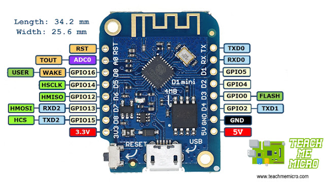
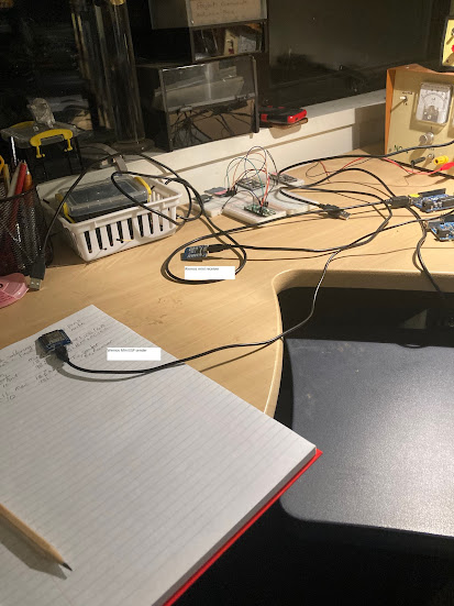
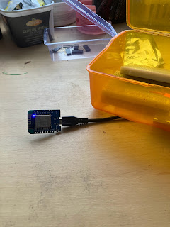
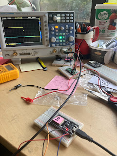
 After trying a couple of programs that didn't work, I found these two: one sender and one receiver. from  github  https://github.com/bnbe-club/esp-now-examples-diy-62/blob/master/controller/controller.ino Here's one of the pastes: https://pastebin.com/xJCJuc6Q LHS, RHS is Wemos MIni 1, the sender, and Wemos Min1 2, the receiver. Worked well off the desk. Next steps are to examine the code and find battery power so that range tests can be done.  Here's the associated YouTube. Here's code for Sender1: /****************************************************************************************************************************************************  /****************************************************************************************************************************************************  *  TITLE: ESP-NOW Getting Started Examples  *  *  By Frenoy Osburn  *  YouTube Video: https://youtu.be/_cNAsTB5JpM  ************************************************************

WEMOs mini going

Image
 Having difficulty soldering NRF24L01 holes to header, very small gaps. So gave up on that for the time being and will concentrate for a while on ESP Now via three Wemos minis I bought recently from TradeMe. Did not install new Jason file etc by following  https://www.teachmemicro.com/getting-started-wemos-d1-mini/ who had different Jason file, but I's previously installed one while I was waiting for Wemos Mini's. Blink sketch went off according to plan and now I want to try out some ESP now functions. First, look at a few You Tubes and look for some functions I can call from ESP now library with just one mini . void setup() {   // initialize digital pin LED_BUILTIN as an output.   pinMode(LED_BUILTIN, OUTPUT); } // the loop function runs over and over again forever void loop() {   digitalWrite(LED_BUILTIN, HIGH);   // turn the LED on (HIGH is the voltage level)   delay(100);                       // wait for a second   digitalWrite(LED_BUILTIN, LOW);    // turn the LED off by
Image
 ESP 32 starting up. Two ESP WROOM 32U boards bought from TradeMe. One of them didn't seem to work. Got blinking on other. Not sure about which pins belong to which GPIO and how you name the pins in the Arduino IDE. Helpful: Oscilloscope, but only showed Hi-Lo edge and not a train of  square waves. Think I've got to do things with the trigger. Finally got blink sketch going on pin.  Also had strange blink results. The one second blink worked well on GPIO13 but not on GPIO9 where there was a short-long train of blinks despite even delay of 1000ms. Maybe it's to do with GPIO9 is a special purpose pin and not for general blinky use. WE see below that GPIO13 is OK, but not GPIO9, as it's part of the SPI.